Arduino Self-Bondage Controller

Ideas and instructions how you can make your own bondage toys.

Would you consider purchasing a custom circuit board to build your own Self-Bondage Controller?

Poll ended at 26 Mar 2020, 21:46

Yes
12
67%
No
1
6%
Maybe
5
28%
 
Total votes: 18

User avatar
Riddle
****
Posts: 1154
Joined: 24 Sep 2008, 08:37
Location: Oregon, USA
Contact:

Arduino Self-Bondage Controller

Post by Riddle »

I am proud to present the Arduino Self-Bondage Controller.
Arduino Self-Bondage Controller
This is a stand-alone Arduino compatible ATmega328P microcontroller programmed to power a release device (electromagnet?) until the timer ends. The prototype only has an LED indicator for output at this time since the magnets are on order from China. The display is either 10 LEDs (5 for minutes, 5 for hours) or an Adafruit.com display module.

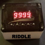
The wiring is fairly simple (especially if you use the display module). Wiring diagram will be provided in the future. The prototype uses a USB cord from a USB battery for power. Four buttons (stop, hours, minutes, start) wired from ground to their respective input pin provide the input. A pull-up resistor to VCC (+5V power) is recommended especially if the buttons are wired away from the circuit board. LEDs are wired from ground to their output pins through a resistor (should be 510 ohm, the prototype is stupid bright with 330 ohms). The display just needs +/- power and 2 data pins. Wire the output through a MOSFET transistor. That is all.

The code is as follows:

Code: Select all

/*  This timer is to time an electromagnet release.
    This version uses the LEDs for the remaining time.
*/

#include <Wire.h> // Enable this line if using Arduino Uno, Mega, etc.
#include "Adafruit_LEDBackpack.h"
#include "Adafruit_GFX.h"

Adafruit_7segment matrix = Adafruit_7segment();


byte hr = 0;
byte mi = 10;
byte sec = 0;
byte start = 0;
byte inByte;

#define OUT 11 // Change in future versions
#define H 4
#define M 6
#define START 8
#define STOP 2
#define M1 10
#define M2 9
#define M3 7
#define M4 5
#define M5 3
#define H1 12
#define H2 A0
#define H3 A1
#define H4 A2
#define H5 A3


int BB = 300;
long interval = 1000;           // interval at which to blink (milliseconds)
long previousMillis = 0;        // will store last time LED was updated
int ledState = HIGH; 
const int ledPin =  13;      // the number of the LED pin
bool displayFlag = true;
volatile byte displayValue [4] = {0,0,0,0};
// Set to true to display time in 12 hour format, or false to use 24 hour:
byte TIME_24_HOUR = true;


void setup() {
  Serial.begin(9600);
  matrix.begin(0x70);
  pinMode(ledPin, OUTPUT);
  pinMode(OUT, OUTPUT);
  pinMode(H1, OUTPUT);
  pinMode(H2, OUTPUT);
  pinMode(H3, OUTPUT);
  pinMode(H4, OUTPUT);
  pinMode(H5, OUTPUT);
  pinMode(M1, OUTPUT);
  pinMode(M2, OUTPUT);
  pinMode(M3, OUTPUT);
  pinMode(M4, OUTPUT);
  pinMode(M5, OUTPUT);
  dtest();
  digitalWrite(H, HIGH);
  digitalWrite(M, HIGH);
  digitalWrite(START, HIGH);
  digitalWrite(STOP, HIGH);
}

void loop() {
  check_buttons();
  mills();
  Display();
  
}


void check_buttons() {
  int hb = digitalRead(H);
  int mb = digitalRead(M);
  int startb = digitalRead(START);
  int stopb = digitalRead(STOP);
  
  if(stopb == LOW && start != 0)
    ESTOP();  
  else if(startb == LOW && start == 0) {
    startt();
  }
  else if(hb == LOW && mb == LOW && start == 0) {
    hr = 0;
    mi = 0;
    sec = 0;
    ttime();
    delay(BB);
   }
  else if(hb == LOW && start == 0) {
    hr ++;
    if(hr > 99)  // Change to number of hour LEDs
      hr = 0;
    delay(BB);
    ttime();
  }
  else if(mb == LOW && start == 0) {
    mi = mi + 10;
    if(mi > 50)
      mi = 0;
    delay(BB);
    ttime();   
  }
  else if(stopb == LOW && start == 0) {
     sec = sec + 30;
     if(sec > 30)
       sec = 0;
     delay(BB);
     ttime(); 
  }
}


void mills() {
    // clock function
   unsigned long currentMillis = millis();
    
  if(currentMillis - previousMillis > interval) {
    cerial();
    // save the last time you blinked the LED 
    previousMillis = currentMillis;
    if (ledState == LOW)
      ledState = HIGH;
    else
      ledState = LOW;
    digitalWrite(ledPin, ledState);
    if(start != 0)
      sec --;
    ttime();
    display_update();
    displayFlag = true;
  }
} 


void ESTOP() {
  digitalWrite(OUT, LOW);
  start = 0;
  hr = 0;
  mi = 0;
  sec = 0;
  dtest();
  delay(5000);
}

void startt() {
  start = 1;
  long x = sec * 1000;
  sec = 0;
  ttime();
  delay(x);
  digitalWrite(OUT, HIGH);
}


void ttime() {  
  if(hr <= 0 && mi <= 0 && sec <= 0 && start == 1)
      ESTOP();
    else if(sec > 59) {
       if(mi > 0) {
         mi --;
         sec = 59;
       }
       else if (hr > 0 && mi == 0) {
          hr --;
          mi = 59;
          sec = 59;
         }
      }

  if(hr == 0) {
    digitalWrite(H1, LOW);
    digitalWrite(H2, LOW);
    digitalWrite(H3, LOW);
    digitalWrite(H4, LOW);
    digitalWrite(H5, LOW);
  }
  else if(hr == 1) {
    digitalWrite(H1, HIGH);
    digitalWrite(H2, LOW);
    digitalWrite(H3, LOW);
    digitalWrite(H4, LOW);
    digitalWrite(H5, LOW);
  }
  else if(hr == 2) {
    digitalWrite(H1, HIGH);
    digitalWrite(H2, HIGH);
    digitalWrite(H3, LOW);
    digitalWrite(H4, LOW);
    digitalWrite(H5, LOW);
  }
  else if(hr == 3) {
    digitalWrite(H1, HIGH);
    digitalWrite(H2, HIGH);
    digitalWrite(H3, HIGH);
    digitalWrite(H4, LOW);
    digitalWrite(H5, LOW);
  }
  else if(hr == 4) {
    digitalWrite(H1, HIGH);
    digitalWrite(H2, HIGH);
    digitalWrite(H3, HIGH);
    digitalWrite(H4, HIGH);
    digitalWrite(H5, LOW);
  }
  else if(hr == 5) {
    digitalWrite(H1, HIGH);
    digitalWrite(H2, HIGH);
    digitalWrite(H3, HIGH);
    digitalWrite(H4, HIGH);
    digitalWrite(H5, HIGH);
  }
  if(mi >= 0 && mi < 10) {
    digitalWrite(M1, LOW);
    digitalWrite(M2, LOW);
    digitalWrite(M3, LOW);
    digitalWrite(M4, LOW);
    digitalWrite(M5, LOW);
  }
  else if(mi >= 10 && mi < 20) {
    digitalWrite(M1, HIGH);
    digitalWrite(M2, LOW);
    digitalWrite(M3, LOW);
    digitalWrite(M4, LOW);
    digitalWrite(M5, LOW);
  }
  else if(mi >= 20 && mi < 30) {
    digitalWrite(M1, HIGH);
    digitalWrite(M2, HIGH);
    digitalWrite(M3, LOW);
    digitalWrite(M4, LOW);
    digitalWrite(M5, LOW);
  }
  else if(mi >= 30 && mi < 40) {
    digitalWrite(M1, HIGH);
    digitalWrite(M2, HIGH);
    digitalWrite(M3, HIGH);
    digitalWrite(M4, LOW);
    digitalWrite(M5, LOW);
  }
  else if(mi >= 40 && mi < 50) {
    digitalWrite(M1, HIGH);
    digitalWrite(M2, HIGH);
    digitalWrite(M3, HIGH);
    digitalWrite(M4, HIGH);
    digitalWrite(M5, LOW);
  }
  else if(mi >= 50 && mi < 60) {
    digitalWrite(M1, HIGH);
    digitalWrite(M2, HIGH);
    digitalWrite(M3, HIGH);
    digitalWrite(M4, HIGH);
    digitalWrite(M5, HIGH);
  }
}


void dtest() {
  matrix.print(0xBEEF, HEX);
  matrix.writeDisplay();
  digitalWrite(H1, HIGH);
  digitalWrite(H2, HIGH);
  digitalWrite(H3, HIGH);
  digitalWrite(H4, HIGH);
  digitalWrite(H5, HIGH);
  digitalWrite(M1, HIGH);
  digitalWrite(M2, HIGH);
  digitalWrite(M3, HIGH);
  digitalWrite(M4, HIGH);
  digitalWrite(M5, HIGH);
}


void Display() {
  if(displayFlag == true) {
    displayFlag = !displayFlag;
  matrix.writeDisplay();
  }
}


void display_update() {
  // set display values to the hours and minutes
  displayValue [0] = hr/10;
  displayValue [1] = hr%10;
  displayValue [2] = mi/10;
  displayValue [3] = mi%10;
  
  if(displayValue [0] == 0) { // check to see if display value equals 0
    matrix.writeDigitRaw(0, displayValue [0]); // blank the digit if zero
  }
  else { // when greater than zero, write the digit
    matrix.writeDigitNum(0, displayValue [0]);
  }
  matrix.writeDigitNum(1, displayValue [1]);
  matrix.writeDigitNum(3, displayValue [2]);
  matrix.writeDigitNum(4, displayValue [3]);
}


void cerial() {
  //the serial stuff goes here.
     // DateTime now = rtc.now();  // Get the time from the RTC IC

   
    Serial.print(hr, DEC);
    Serial.print(':');
    Serial.print(mi, DEC);
    Serial.print(':');
    Serial.print(sec, DEC);
    Serial.println();
   
}
What are your thoughts? What features and changes would you suggest? Do you want a custom circuit board to make wiring faster and easier?
Resident timer maker. :hi:
Let’s make timers together!
User avatar
Riddle
****
Posts: 1154
Joined: 24 Sep 2008, 08:37
Location: Oregon, USA
Contact:

Re: Arduino Self-Bondage Controller

Post by Riddle »

The parts used are as follows:

Adafruit Metro Mini
https://www.adafruit.com/product/2590
Any Arduino Uno or other ATMega328P will work.

Adafruit Display
https://www.adafruit.com/product/1268 (actually used)
https://www.adafruit.com/product/880 (recommendation)

Adafruit Proto board
https://www.adafruit.com/product/1214

Adafruit Buttons
https://www.adafruit.com/product/1489

AliExpress Electromagnet (on order)
https://www.aliexpress.com/item/3281580 ... 4c4d5Oe7af

MOSFET logic level control
RFP12N10L

Generic green LEDs

Generic resistors

Generic header
Resident timer maker. :hi:
Let’s make timers together!
Nudy
*
Posts: 1
Joined: 31 Jul 2016, 22:27

Re: Arduino Self-Bondage Controller

Post by Nudy »

Nice project, I considder building this,
I am intrested in the wiring diagram as well.
tnx. Nudy
User avatar
Shannon SteelSlave
Moderator
Posts: 6596
Joined: 03 Feb 2019, 19:49
Location: New England, USA

Re: Arduino Self-Bondage Controller

Post by Shannon SteelSlave »

Thanks for your reply, Nudy, and a late welcome, to Bound Anna.
Bondage is like a foreign film without subtitles. Only through sharing and practice can we hope to understand.
A Jedi uses bondage for knowledge and defense, never for attack.
I am so smart! I am so smart! S-M-R-T!....I, I mean S-M-A-R-T!
👠👠
User avatar
GeneralError
**
Posts: 141
Joined: 16 Sep 2019, 15:30
Location: Germany

Re: Arduino Self-Bondage Controller

Post by GeneralError »

Cool stuff!
I like it!
User avatar
Shannon SteelSlave
Moderator
Posts: 6596
Joined: 03 Feb 2019, 19:49
Location: New England, USA

Re: Arduino Self-Bondage Controller

Post by Shannon SteelSlave »

impressive.jpg
impressive.jpg (48.88 KiB) Viewed 5420 times
Bondage is like a foreign film without subtitles. Only through sharing and practice can we hope to understand.
A Jedi uses bondage for knowledge and defense, never for attack.
I am so smart! I am so smart! S-M-R-T!....I, I mean S-M-A-R-T!
👠👠
User avatar
Gregovic
****
Posts: 1119
Joined: 26 Mar 2016, 21:31
Location: Netherlands

Re: Arduino Self-Bondage Controller

Post by Gregovic »

I might consider purchasing a custom board, but it would depend on the cost and the size of the complete assembly.
How may I serve you? *Curtsey*
User avatar
Riddle
****
Posts: 1154
Joined: 24 Sep 2008, 08:37
Location: Oregon, USA
Contact:

Re: Arduino Self-Bondage Controller

Post by Riddle »

Arduino Self-Bondage Controller
Attached is the wiring diagram for the controller.

Don’t forget the resistors for the MOSFET and the flyback diode on the electromagnet.
Last edited by Riddle on 31 Dec 2019, 13:27, edited 1 time in total.
Resident timer maker. :hi:
Let’s make timers together!
User avatar
Riddle
****
Posts: 1154
Joined: 24 Sep 2008, 08:37
Location: Oregon, USA
Contact:

Re: Arduino Self-Bondage Controller

Post by Riddle »

Is anyone planning to use the LEDs for the time remaining info? Or is everyone wanting to use a digital clock display?

How many MOSFET outputs are needed? I am thinking at least 2.
Resident timer maker. :hi:
Let’s make timers together!
User avatar
Gregovic
****
Posts: 1119
Joined: 26 Mar 2016, 21:31
Location: Netherlands

Re: Arduino Self-Bondage Controller

Post by Gregovic »

Since a digital (8-segment) display is much easier to read I'd probably go with that option.
How may I serve you? *Curtsey*
Onwrikbaar
**
Posts: 95
Joined: 21 Sep 2018, 17:17
Location: The Netherlands
Contact:

Re: Arduino Self-Bondage Controller

Post by Onwrikbaar »

And don't forget to add a flyback diode to prevent the magnet's inductance from causing a voltage spike at switch-off that may destroy the FET.
User avatar
Riddle
****
Posts: 1154
Joined: 24 Sep 2008, 08:37
Location: Oregon, USA
Contact:

Re: Arduino Self-Bondage Controller

Post by Riddle »

Is there anyone who wants the individual LEDs for showing the time remaining? If no one speaks up, I will forget about them.

Onwrikbaar wrote:And don't forget to add a flyback diode to prevent the magnet's inductance from causing a voltage spike at switch-off that may destroy the FET.
Thank you for the reminder.
Resident timer maker. :hi:
Let’s make timers together!
User avatar
pavtron
**
Posts: 147
Joined: 19 Dec 2012, 22:38

Re: Arduino Self-Bondage Controller

Post by pavtron »

Riddle wrote:Is there anyone who wants the individual LEDs for showing the time remaining?
I like the idea of the LEDs vs a time display. I guess it would just depend on what you where going for that session.
User avatar
Riddle
****
Posts: 1154
Joined: 24 Sep 2008, 08:37
Location: Oregon, USA
Contact:

Re: Arduino Self-Bondage Controller

Post by Riddle »

pavtron wrote:
Riddle wrote:Is there anyone who wants the individual LEDs for showing the time remaining?
I like the idea of the LEDs vs a time display. I guess it would just depend on what you where going for that session.
Ok. I will design a module that uses the LEDs for the display output.
Resident timer maker. :hi:
Let’s make timers together!
User avatar
Riddle
****
Posts: 1154
Joined: 24 Sep 2008, 08:37
Location: Oregon, USA
Contact:

Re: Arduino Self-Bondage Controller

Post by Riddle »

Any suggestions for the LED time indicator? How many LEDs? Is 12 good (6 for minutes, 6 for hours)? Any issue with it being a I2C module using a MCP23017?
Resident timer maker. :hi:
Let’s make timers together!
Post Reply